Conclusions
Geophysical prospecting carried out in the area of the Liberta Peticia villa enabled the collection of a number of archaeologically and topographically interesting data.
Net of the impossibility of covering a homogeneous unobstructed area, it was possible to point out the presence of a number of anomalies, the most interesting of which are those related to probable structures located to the south of the main building and most likely forming part of outbuildings related to it.
The depth of the anomalies referable to masonry structures is certainly compatible with those of the villa, suggesting that they belong to the same chronological scope.
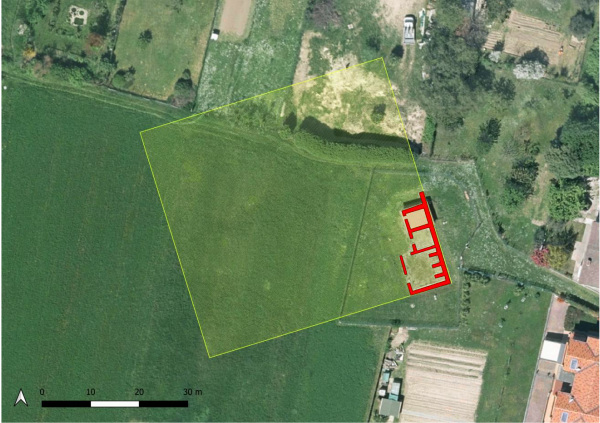
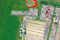
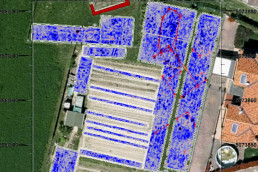
A second important fact to take into account is the lack of anomalies referable to masonry structures in the area immediately south of the villa and thus in physical connection with it. This fact seems to prove that the rooms identified during excavation represent the southeastern limit of the building and that the remaining rooms of the villa are to be sought toward the north and in the field west of it, as assumed in the image below.
Results
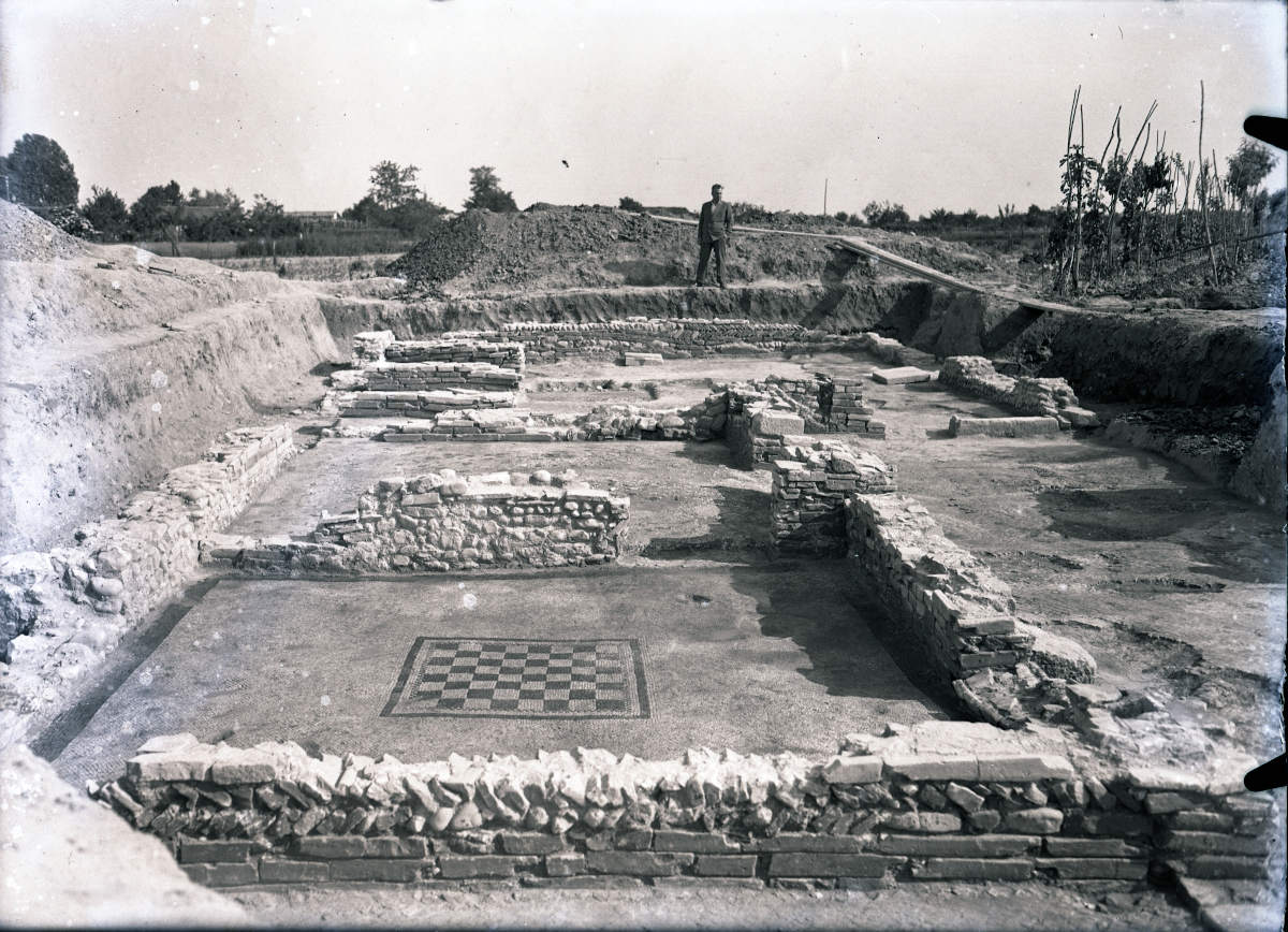
The structures related to the villa identified during the excavation phase are represented by at least three rooms aligned on a southeast/northwest axis open to a probable uncovered area located to the west of them.
The structure shows at least three phases of renovation, in the last of which, the largest room located south and st of the structure and recognized as a triclinium, was subdivided into smaller rooms.
The characteristics of the identified wall structures, the lack of openings along the east and south walls of the rooms and of traces of walls on the external face, seem to indicate that the portion of the villa discovered is the one related to the southeastern corner, and that it therefore developed towards the north and west, for an estimated extension d i 2500 square meters.
The archaeological data recovered as a result of the excavations would thus seem to validate the hypothesis that in the area south of the structures there may be no masonry structures belonging to the main body of the villa, a theory that does not, however, imply the lack of buildings or outbuildings pertaining to the villa but not physically connected to it.
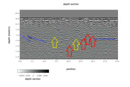
Georadar surveys have identified some interesting anomalies at an average depth estimated between 60 to 1 meter in depth, the same elevation at which the ridges of the identified structures stand.
The data were interpreted in order to identify any anomalies attributable to buried structures of archaeological interest.
Data processing identified three distinct groups of anomalies located at different depths from 40-50 cm above ground level, all in the eastern range of the field.
The anomalies were classified according to their type, stratigraphic position, and geometry.
It should be pointed out that an error in depth of +/-0.15-0.20m should be considered for depth and -/+0.10-0.15m for width of anomalies, due to instrument resolution, interference and possible systematic errors.
Tables
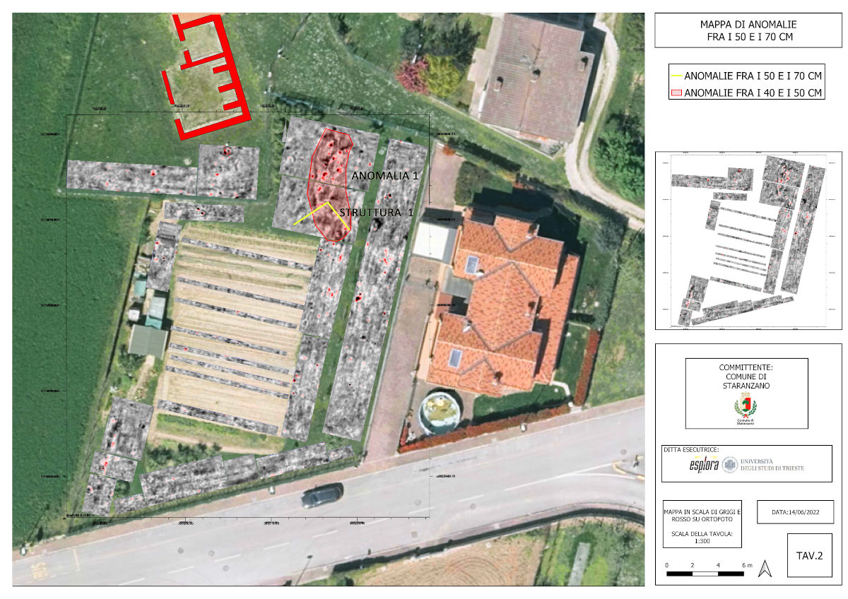
Table 1 - Depth between 40 and 50 cm: In the northeastern part of the field, immediately southeast of the villa structures, an irregularly shaped anomaly appears at a depth of about 50 cm, running from north to south covering an area of about 60 square meters (see below image 'longitudinal and cross sections of Anomaly 1').
From its shape and development in depth, the anomaly is funnel-shaped and could be associated with a pit filled with inconsistent material, probably a post-depositional intervention that also affected the underlying archaeological levels.
It is conceivable that it can be explained as an intervention of destruction or spoliation of underlying structures.
The hypothesis could be supported by the presence in the same area, from 50 cm depth, of traces of linear anomalies that, descending in the stratigraphy, assume a more linear geometry, revealing themselves as probable wall structures related to a building located southeast of the villa structure.
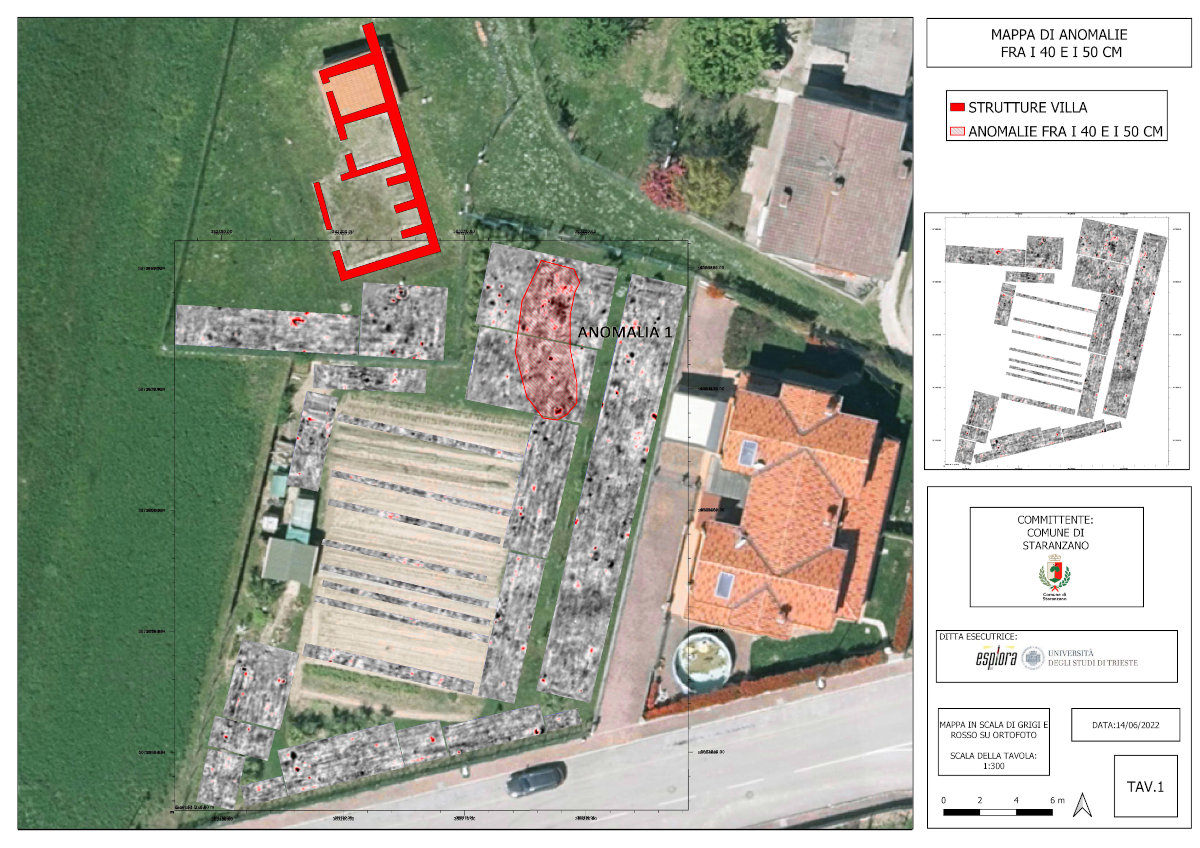
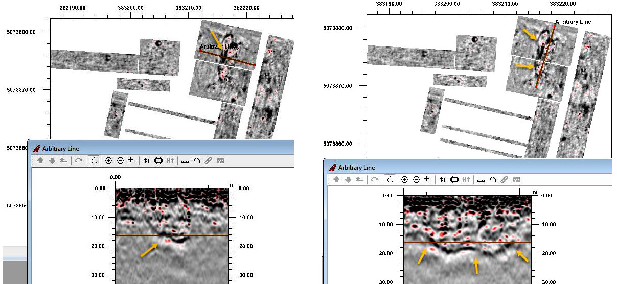
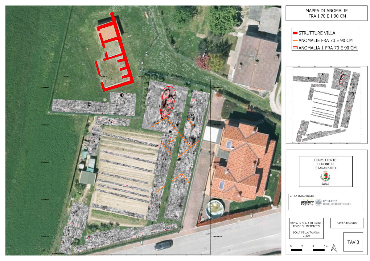
Table 2 and Table 3 - Depth between 70 and 90 cm: At this depth the wall structures identified in the higher levels take on a more precise physiognomy, while the trench reaches maximum visibility before disappearing around the depth of 1.20 m. From 70 cm other linear and isoriented anomalies are added to those already highlighted in the higher levels, probably as a matter of preservation of the elevations.
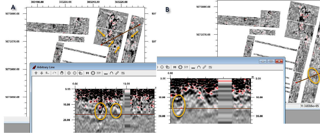
In more detail, the first building (see below image 'A evidence from Structure 1) seems to be characterized by two longer walls with a northwest/southeast orientation (the east one is visible in its entirety), at the ends of which are two smaller arms perpendicular to these: the space created by these walls seems to be further divided into two rooms by an intermediate wall septum. At the level of the southeastern head of the east wall of the building we seem to see the trace of an additional structure running eastward and extending the southern limit of the building on this side. East of the longer wall is the trace of a further wall alignment, parallel to it and probably pertaining to the eastern limit of a third room. Of the second building (see image 'B evidence of Structure 2' below), located to the south of this one, a long wall is identifiable that runs parallel to the south side of the first, and a second structure that creates a 90-degree angle to the southeast, starting from the east head of this one.
The sign is less legible than that for the first building, probably because of the level of preservation.
At this depth it is therefore possible to reconstruct the presence of at least two buildings, oriented toward each otherand not physically connected to the main body of the villa.
The orientation of the identified buildings also does not reflect that drawn by the walls exposed in the excavation, although this element does not collide with a direct relationship between the structures.
Depths between 90 and 120 cm: the signals related to the first structure are readable up to a depth of 1.10 m, after which it becomes more difficult to read its geometry. As for the anomaly related to the ditch, this is clearly identified at least up to a depth of 1.20 m, and then gradually disappears.
Data processing
3D GPR data are processed in order to recreate a volume in x,y spatial coordinates and z (depth) in temporal coordinates or converted to depth.
Each recording involves the acquisition of 8 profiles simultaneously, so that the information obtained is that of a 64cm band.
The raw data (raw data) to be processed is then a number of "bands" equal to the number of profiles run.
The raw data undergoes a pre-processing step to improve the signal-to-noise ratio; the processing steps that are applied to the data set is as follows:
- Amplitude correction
- Antenna Ringdown removal
- Bandpass filtering
Next comes the interpolation phase, in order to integrate information between records. This is done by selecting a box, within which the interpolation algorithms will take place.
Depth conversion is done after estimating the velocity of the electromagnetic wave in the medium according to the diffraction hyperbole analysis procedure, and the subsequent migration procedure. The velocity measurement is made on the basis of the analysis of diffraction hyperbolas, the aperture of which depends on the dielectric constant of the medium and thus the velocity of the electromagnetic wave.
At this site, however, no hyperbola was found on which to estimate the propagation velocity. A velocity of 10.5 cm/ns was estimated under these conditions, based on analysis of diffraction hyperbolas.
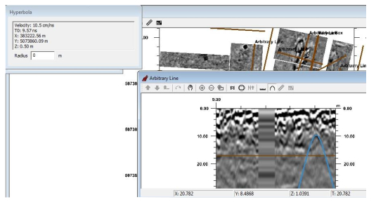
The migration procedure results in a GPR image for which the anomalies are higher resolution and in which the diffraction hyperbolas are focused into point units.
After the migrated volume is obtained, the software allows the entire area covered by the GPR to be analyzed in plan as a function of depth and the different maps (slices) to be analyzed and then proceeded with interpretation.
To recap, the processing sequence applied to the data volume includes:
Import raw data
• DC removal
• Drift removal
Pre-processing
• Amplitude correction
• Antenna Ringdown removal
• Bandpass filtering
Processing
• Interpolation
• Migration
Post processing
• Amplitude analysis
• Slice interpretation
Data acquisition
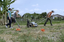
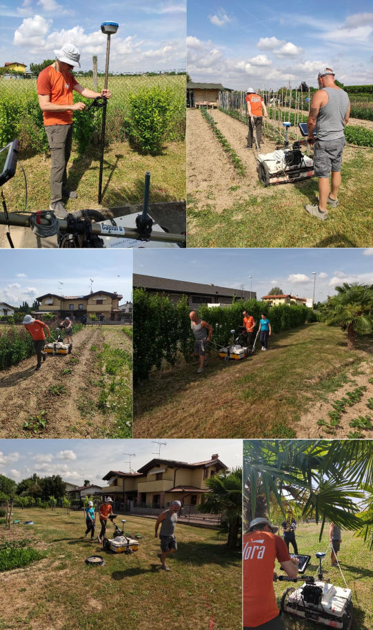
3D Georadar data acquisition was performed in the vacant area located south of the archaeological area on May 24, 2022.
A GNSS ( Global Navigation Satellite System) receiver was used for GPS positioning, connected via GPRS (General Packet Radio Service) to the NRTK (Network Realtime Kinematic Satellite) differential real-time corrections network. The GNSS receiver was installed directly on the Georadar apparatus.
Georeferencing was performed in the WGS84 coordinate system UTM33N zone thanks to the in situ topographic survey of some evidences in the area.
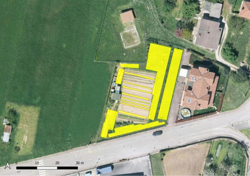
The purpose of the survey was to identify the presence of additional masonry structures belonging to the villa in the only area for now that can be traversed with Georadar.
In fact, the archaeological area is surrounded by land belonging to private individuals, some of which is built-up and difficult to traverse with this instrumentation.
The same area covered by prospecting had a number of problems, related to the presence of areas planted with vegetable gardens, and a part occupied by some service sheds.
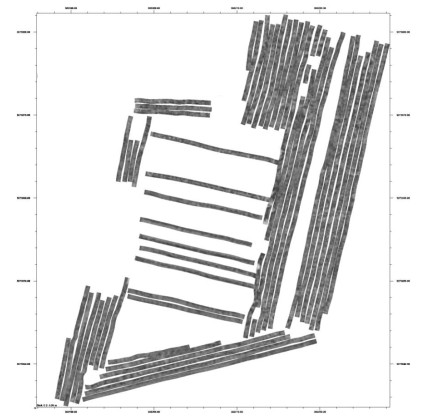
As a result, the particular lay of the land did not allow for complete coverage of the area, covering an area of about 730 square meters.
Parametri utilizzati per il rilevo Georadar
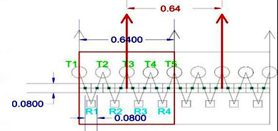
- Frequency Shielded antennas: 400MHz
- Total antenna offset: 0.64m
- Number of channels: 8
- Communication: Ethernet
- Positioning: GPS-RTK and odometer
- Power supply: 12V 45Ah battery
- Spatial sampling interval: 0.08m
- Number of samples per track: 436
- Time window length: 97.26ns
- Vertical stack: 4
Georadar GPR survey: physical principles
To finalize the 3D geophysical investigations, we made use of ground penetrating radar (GPR) georadar, which allows us to investigate both the subsurface and structures and noninvasively reveal the possible presence and location of buried objects, metal objects, and anomalies in masonry structures using the phenomenon of electromagnetic wave reflection.
The method of analysis is based on the principle of propagation of electromagnetic pulses in materials and their reflection at those discontinuity surfaces attributable to changes in permectivity of the materials investigated.
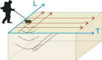
Data acquisition is accomplished by sliding a pair of antennas (one transmitter and one receiver) maintained at a constant distance over the surface to be investigated.
In the central unit of the apparatus, signals are generated at regular intervals that serve to stress the electronic circuits of the transmitting antenna.
Electromagnetic pulses are radiated from this, which, propagating through materials, are reflected at the interfaces between materials with different dielectric characteristics.
Reflected events are picked up by the receiving element and sent into the central unit for further processing.
The equipment allows real-time display of the recorded radargram on a color display for preliminary quality control, and simultaneously stores the data on associated notebook for later processing with dedicated software.
Subsequent digital processing of the data makes it possible to improve the interpretability of the acquired data through filtering operations, normalization, amplification, etc. in order to make the presence of any anomalies more obvious.
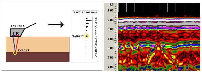
On the horizontal axis of the radargrams are displayed the metric progressions of the recorded line, while on the vertical axis are the double path times (outward and return) of the reflected paths.
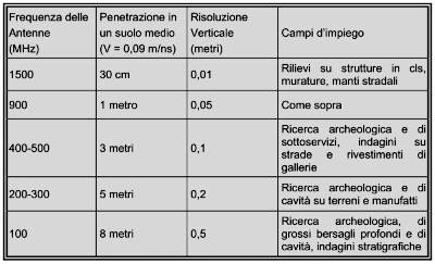
The horizontal resolution of the signals is inversely proportional to the speed at which the antenna is moved; the vertical resolution is directly proportional to the center frequency of the emitted pulses.
The intensity of reflected events is stronger the greater the contrast between dielectric variations.
The depth of investigation cannot be established a priori of the survey but depends on the absorption of electro magnetic energy by the materials in which it propagates. The depth depends on the nature of the media traversed, the physical state of the constituent elements, and environmental and/or local factors: temperature, humidity, presence of cavities, etc.
Moreover, the prospecting target and penetration depth are constrained by the wavelength of the pulses: in fact, if a buried structure is very small in size, it is detected only with signals of very short duration whose high attenuation at the energy level, however, limits its penetration.
In summary, antennas with high frequencies allow good resolution down to modest depths; antennas with low frequencies offer relatively less detail, but allow a greater extent of measurement from the surface topography.
The presence of water or moisture in the materials under examined, results in an increase in the relative dielectric constant and thus a decrease in the speed of electromagnetic pulses. Knowledge of the relative dielectric constant is useful in determining the type of material being investigated and its degree of moisture.
The definition of such anomalies is provided at the data interpretation stage, based on the type (e.g., shape of the object that caused the reflection) and planimetric continuity of identical or, at any rate, similar events.
It is important to remember that the measurement procedures used for the geophysical survey of Villa Peticia are based on indirect exploration techniques that have a number of inherent limitations regarding the propagation of the electromagnetic wave. This wave depends on the dielectric constant of the materials: in clay materials with high dielectric constant or in the presence of water, the attenuation of the signal is high with the risk of not detecting any discontinuities/objects present.
The geophysical survey cannot all way never be considered a complete substitute for direct exploration.
The Georadar system used
A 3D georadar system, equipped with 9 shielded antennas at 400MHz, was used in the present investigation for exploration depths within 3m.
The system encloses within it 5 transmitting and 4 receiving antennas of the same frequency, and the combination of transmitting and receiving causes 8 parallel profiles to be obtained simultaneously at each pass.
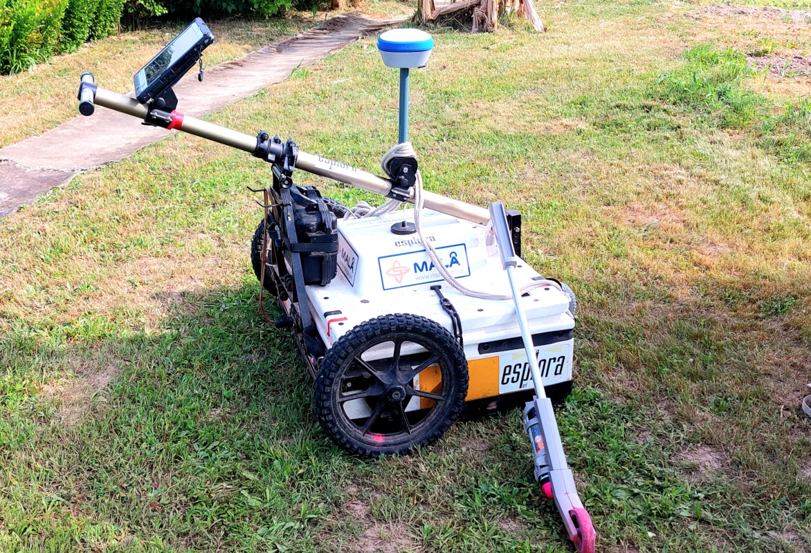
The 8 profiles are spaced by a fixed offset of 8cm. Together they occupy a 64cm band. The positioning system involves the use of an odometer and where possible interfacing with GPS or total station.
This very complex system was developed to identify archaeological finds quickly and with very high resolution.
The system facilitates the interpretation of the signal by highlighting continuous structures, and avoids making errors in interpolations of 2-dimensional profiles.
Acquisition in the 3 directions of space makes acquisition independent of the often unknown orientation of the target.
The 3D system is connected to a laptop from which acquisition parameters can be managed and the acquisition of each swipe can be viewed in real time.
The technological limit ical limitation of the 2D and 3D georadar methodology, in each case is the depth of the water table, since it completely absorbs the electromagnetic signal.